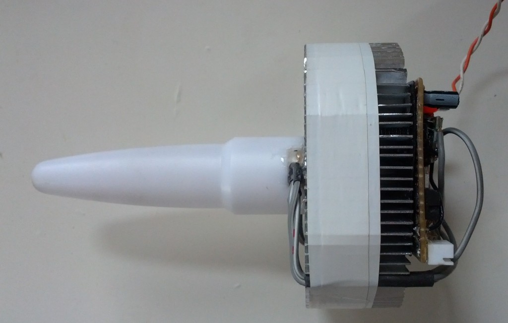
This is an RGB Lamp assembly that I constructed based around the following parts:
- Atmel ATmega8 MCU
- ADXL345 triple axis accelerometer
- 10W RGB LED
- ~350mA LED driver x 3
- Beam diffuser
- 10W LED heatsink
The idea is that the accelerometer is used to calculate the lamp position in spherical polar coordinates, which are then used to control the colour of the lamp. The LED is driven by 3 switching converters coupled to the PWM outputs of the ATmega8 through opto-isolators.
Anyway, enough details, here's a video of the lamp in action:
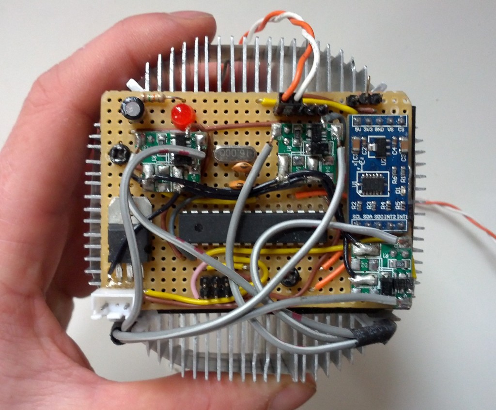
And for those interested in the circuitry (picture taken prior to adding optos):
The blue board on right is the ADXL345 break out board, which also features a selectable 3.3V regulator and TWI pull up resistors. In this case the regulator is used because the ATmega8 I had lying around requires a minimum of 4.5V. Fortunately the SDA and SCL lines of the TWI bus are open drain so there's no need to worry about level conversion in this case. I was actually surprised at just how good the ADXL345 is. Not only does it have some cool stuff like tap detection, with a little bit of software filtering I can comfortably get an angular resolution of ~0.25 degrees after the conversion to spherical polars.
Also seen on the above picture are three little green boards which are the LED drivers, hooked up directly to the DC input in the bottom left hand corner which is 16V. Originally I built my own switching converter, but it actually worked out cheaper (and faster!) to modify modules from DX by removing the rectifier and soldering a wire directly to PT4115 dimming pin for brightness control. Obviously, it's a good idea to use an opto-isolater between the dimming pin and the MCU, not only in case the PT4115 fails, but because the dim pin registers ~5.3V and is about 1mm from the 16V supply!
Other things that you see are an ISP header in the lower middle, 16MHz crystal in the centre, an LED in the top left, and switch connection / UART headers in the top right. The UART header was used for debugging with a CP2102 USB to UART bridge. These are awesome little modules which are well worth investing in, especially if you don't have a debugger.
The code for the project is now available here:

