CAT3626 RGB LED Driver + Qt Embedded 4.6 on the Mini2440
The CAT3626 is a nice little I2C device from ON Semiconductor. It comes in a 14 pin TQFN package which is probably the most difficult thing i've ever soldered! Each pad is separated from it's neighbour by about 100 micrometers! To make matters even more difficult there's a ground pad right in the middle for sinking heat away. Really you should get some sort of breakout board or reflow it but that would be boring! Here's a picture of the device before soldering:

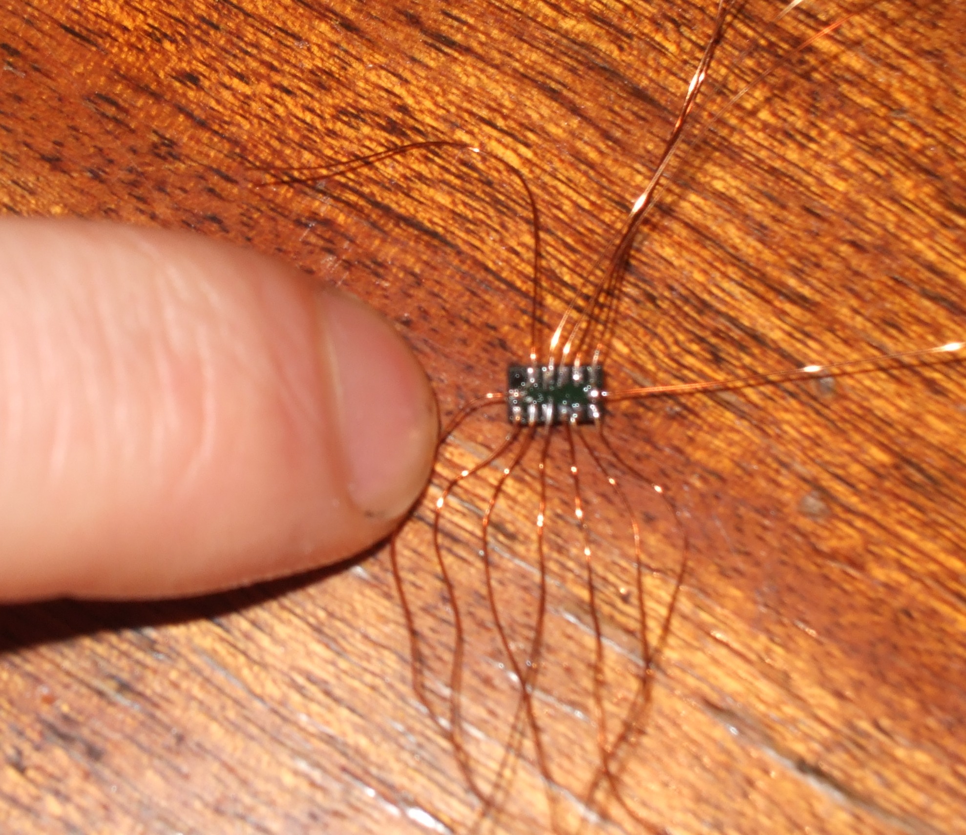
...and here's the finished product! The LED is 10mm diffuse with a common anode and a maximum current rating of 20mA per channel. As soon as i'd soldered the wires to the CAT3626 i glued it to the board with epoxy, threaded the wires through the holes and then glued those down with more epoxy. After that i realised i'd forgotten where pin 1 had gone so i had to scrape the glue off the top of the chip!


The wire coming through the hole in the middle of this picture is soldered to the CAT3626 and acts as a crude heat sink. In practice it seems to work well enough although i probably should have used copper. I pulled the ceramics from an old projector i had lying around. Not the neatest job but it works fine!
After I'd built that i tested it quickly using I2C tools and then wrote a kernel driver. The CAT3626 allows a maximum of 32mA per channel regulated in steps of 0.5mA. Unfortunately because my LED can take a maximum of 20mA per channel i can only generate ~64,000 colours. To make matters worse the light intensity is not in general a linear function of the input current so the achievable fade sequences are not as nice as those done with PWM but they still look pretty good. Here's a video!
Update: The kernel driver for the CAT3626 is now available for free on github!
Chameleon 135 for the Mini2440
Thanks to www.andahammer.com both Will and I now have the Chameleon 135 enclosure for the Mini2440. I've been working on a li-ion charger and once that's finished we should be ready for some field testing. It takes a little while to get the holes drilled in the right place but once it's screwed together the case is extremely sturdy. There's loads of room inside for additional wiring :)

You can get the Chameleon from www.andahammer.com.
Bluetooth GPS on the mini2440 with GPSd
For a long time i've had a SiRF 3 bluetooth GPS which i've just connected to the mini2440 using a ludicrously cheap USB bluetooth adapter from DealExtreme. Including shipping it cost £1.38 delivered!! Here's what you get for your money:


The chip is a Conwise CW6626. Anyway, what matters most is that if you have bluetooth configured it works out of the box!
Connecting to the GPS is easy. First check the interface:
hciconfig -a
If it says down bring it up:
hciconfig hci0 up
After executing the above I got the following:
root@mini2440:~# hciconfig -a
hci0: Type: USB
BD Address: 00:15:83:15:A3:10 ACL MTU: 672:3 SCO MTU: 128:2
UP RUNNING
RX bytes:348 acl:0 sco:0 events:11 errors:0
TX bytes:38 acl:0 sco:0 commands:11 errors:0
Features: 0xff 0x3e 0x85 0x30 0x18 0x18 0x00 0x00
Packet type: DM1 DM3 DM5 DH1 DH3 DH5 HV1 HV2 HV3
Link policy:
Link mode: SLAVE ACCEPT
Name: ''
Class: 0x000208
Service Classes: Unspecified
Device Class: Phone, Cordless
HCI Ver: 2.0 (0x3) HCI Rev: 0xc5c LMP Ver: 2.0 (0x3) LMP Subver: 0xc5c
Manufacturer: Cambridge Silicon Radio (10)
Now turn your GPS on and do a scan:
root@mini2440:~# hcitool scan
Scanning ...
00:0D:B5:32:2C:02 BT-GPS-322C02
Now fill in /etc/bluetooth/rfcomm.conf with the details. Here's mine:
#
# RFCOMM configuration file.
#
rfcomm0 {
# Automatically bind the device at startup
bind yes;

# Bluetooth address of the device
device 00:0D:B5:32:2C:02;

# RFCOMM channel for the connection
channel 1;

# Description of the connection
comment "BT-GPS-322C02";
}
Next bind the device:
rfcomm bind rfcomm0
And check the device output using:
cat /dev/rfcomm0
Next i bitbaked gpsd, by simply typing:
bitbake gpsd
In my OE installation (see the various posts about setting this up).
Once this builds you can install the appropriate ipks. From memory I think i installed the following:
gpsd_2.39-r0.5_armv4t.ipk

gpsd-static_2.39-r0.5_armv4t.ipk

gpsd-gpsctl_2.39-r0.5_armv4t.ipk

gps-utils_2.39-r0.5_armv4t.ipk

libgps18_2.39-r0.5_armv4t.ipk
This pulled in a whole load of other packages. Next you can start gpsd by typing:
gpsd /dev/rfcomm0
And monitor the output using:
gpsmon
If all has gone well you should get a text output of the parsed NMEA data:

Anyway..that's just the tip of the iceburg. If you want to learn more have a look at the gpsd website and the bluetooth page i have based this post on.
Bitbaking the kernel, Angstrom and qt4-embedded all at once
This is what i should have done to begin with! The instructions are very similar to previous ones except this time we clone the right git repository!
On a fresh copy of Fedora 11 I updated the system and installed the packages reccommended by OE:
su -c “yum install python m4 make wget curl ftp cvs subversion tar bzip2 gzip unzip
python-psyco perl texinfo texi2html diffstat openjade docbook-style-dsssl
docbook-style-xsl docbook-dtds docbook-utils sed bison bc glibc-devel glibc-static
gcc binutils pcre pcre-devel git quilt groff linuxdoc-tools patch linuxdoc-tools
gcc-c++ help2man perl-ExtUtils-MakeMaker”
I then made a folder called OE in my home directory and git cloned the mini2440 repo:
cd ~
mkdir OE
cd OE
git clone git://repo.or.cz/openembedded/mini2440.git openembedded
I then setup the source-me.txt similar to before:
gedit source-me.txt
I put the following in:
export OETREE="/home/doug/OE"

BBPATH=${OETREE}/:${OETREE}/openembedded/

echo Setting up dev env for Ångström

if [ -z ${ORG_PATH} ] ; then
ORG_PATH=${PATH}
export ORG_PATH
fi

if [ -z ${ORG_LD_LIBRARY_PATH} ] ; then
ORG_LD_LIBRARY_PATH=${LD_LIBRARY_PATH}
export ORG_LD_LIBRARY_PATH
fi

PATH=${OETREE}/openembedded/bitbake/bin:${ORG_PATH}

LD_LIBRARY_PATH=
export PATH LD_LIBRARY_PATH BBPATH
export LANG=C
export BB_ENV_EXTRAWHITE="MACHINE DISTRO OETREE ANGSTROM_MODE ANGSTROMLIBC LIBC"

su -c 'sysctl vm.mmap_min_addr=0'

echo "Altered environment for OE Development"
Now all you need to do is setup the local.conf. Simply edit the example and copy it to the right place:
cd openembedded
gedit mini2440_local_conf_example.conf
Read this file and edit as appropriate. I have attached mine as an example. Now copy it to the conf/local.conf
cp mini2440_local_conf_example.conf conf/local.conf
If you want qt4-embedded or any other package included in the build simply edit the recipe in:
openembedded/recipes/images/mini2440-image.bb
I added qt4-embedded:
#Angstrom bootstrap image

IMAGE_PREPROCESS_COMMAND = "create_etc_timestamp"

ANGSTROM_EXTRA_INSTALL ?= ""

DEPENDS = "task-base-extended
psplash-zap
esekeyd u-boot-utils tslib
i2c-tools i2c screen rsync nfs-utils
directfb gdbserver directfb mtd-utils
"

IMAGE_INSTALL = "task-base-extended
${ANGSTROM_EXTRA_INSTALL}
psplash-zap qt4-embedded
esekeyd u-boot-utils tslib-calibrate tslib-tests
i2c-tools i2c screen rsync nfs-utils-client
directfb gdbserver directfb mtd-utils
rsvg pango
"

export IMAGE_BASENAME = "mini2440-image"
IMAGE_LINGUAS = ""

inherit image
Then all you have to do is source the script from wherever you put it:
source source-me.txt
and run bitbake:
bitbake mini2440-image
from the ~/OE/openembedded/ directory..
If you get an error trying to build a package try cleaning it:
bitbake -c clean INSERTPACKAGENAME
Then try and build the image again. Maybe you won't have this problem. I guess it's either because the checksum parser failed to build or my hdd is dodgy. It only happened once on binutils but worked fine after cleaning it.
A few hours later if all goes well you should have images in:
~/OE/oetmp/deploy/glibc/images/mini2440/
Obviously that directory depends on what you setup in the local.conf.
Good luck!
Configuring Open Embedded to bake Angstrom images for the mini2440
Please Note: I noticed a few people were having trouble with the Angstrom build using Doug's article, so I thought I'd post the exact method I used (which seemed to work!) so others can retrace my steps with out confusing anyone by editing the previous article! If you have already successfully baked an Angstrom image please ignore this post!
First off I'd like to point out that this article is essentially an amalgamation of the Open Embedded Wiki (Getting Started) and Angstrom's 'Building Angstrom' articles but in context relating to the mini2440 Embedded PC. If you would like a more detailed and probably better written explanation please refer to these two articles.
Make sure you have the packages needed for Open Embedded(OE) by visiting here and looking under the section relating to your distro. Running fedora 11 I did:
su -c "yum install python m4 make wget curl ftp cvs subversion tar bzip2 gzip unzip
python-psyco perl texinfo texi2html diffstat openjade docbook-style-dsssl
docbook-style-xsl docbook-dtds docbook-utils sed bison bc glibc-devel glibc-static
gcc binutils pcre pcre-devel git quilt groff linuxdoc-tools patch linuxdoc-tools
gcc-c++ help2man perl-ExtUtils-MakeMaker"
Getting down to business...
Open up a terminal. Issue these commands:
su -
mkdir -p /stuff2/build/conf
chmod 777 -Rf /stuff2/
exit
cd /stuff2/
Download latest bitbake from here and extract the bitbake directory in the archive (eg. bitbake-1.8.16) to /stuff2/
A few more commands:
mv bitbake-1.8.16/ bitbake
git clone git://git.openembedded.org/openembedded
cp openembedded/conf/local.conf.sample build/conf/local.conf
Edit the config you have just copied using your favourite text editor.
gedit build/conf/local.conf
It is important that you read the config carefully so that you understand what everything does...
Next edit it to look something like this (which is just a slightly modified version of openembedded/contrib/angstrom/local.conf) :
Note: Do not copy and paste from this article due to formatting issues. You can download a pre-made local.conf here.Just extract to /stuff2/build/conf/ ...
MACHINE = "mini2440"

# Where to store sources
DL_DIR = "/stuff2/downloads"

INHERIT += " rm_work "

# Make sure you have these installed
ASSUME_PROVIDED += "gdk-pixbuf-csource-native imagemagick-native librsvg-native"

# Which files do we want to parse:
BBFILES := "/stuff2/openembedded/recipes/\*/\*.bb"
BBMASK = ""

# What kind of images do we want?
IMAGE_FSTYPES += " tar.bz2 "

# Set TMPDIR instead of defaulting it to $pwd/tmp
TMPDIR = "/stuff2/${DISTRO}-dev"

# Make use of SMP and fast disks
PARALLEL_MAKE = "-j2"
BB_NUMBER_THREADS = "2"

#tinderbox
#INHERIT += "oestats-client"
OESTATS_BUILDER = "myname"

DISTRO = "angstrom-2008.1"
Save and exit the editor. Download this script and move it to the directory /stuff2/ .
Check it is ok:
gedit /stuff2/source-me.txt
It should look something like this:
export OETREE="/stuff2"
export PATH=/stuff2/bitbake/bin:$PATH
BBPATH=${OETREE}/:${OETREE}/build/:${OETREE}/openembedded/
PKGDIR=${OETREE}/build/
DL_DIR=${OETREE}/downloads
echo Setting up dev env for Ångström

if [ -z ${ORG_PATH} ] ; then
ORG_PATH=${PATH}
export ORG_PATH
fi

if [ -z ${ORG_LD_LIBRARY_PATH} ] ; then
ORG_LD_LIBRARY_PATH=${LD_LIBRARY_PATH}
export ORG_LD_LIBRARY_PATH
fi

PATH=${OETREE}/openembedded/bitbake/bin:${ORG_PATH}

cd $PKGDIR

LD_LIBRARY_PATH=
export PATH LD_LIBRARY_PATH BBPATH
export LANG=C
export BB_ENV_EXTRAWHITE="MACHINE DISTRO OETREE ANGSTROM_MODE ANGSTROMLIBC LIBC"

echo "Altered environment for OE Development"
save, and start the script:
cd /stuff2/
source source-me.txt
cd ../openembedded
one last update:
git pull
Issue a few commands to fix build issues:
su
sysctl vm.mmap_min_addr=0
setenforce 0 (Fixes an SELINUX problem during building)
exit
issue build commands:
bitbake base-image ; bitbake console-image ; bitbake x11-image
Be prepared to saturate your internet connection, wait a long time and take up a lot of disk space! The result ends up in:
stuff2/angstrom-dev/deploy/glibc/images/mini2440
You should have the image(s) in .jffs2 for flashing and .tar.gz for mounting using NFS.
New hardware!
After breaking the z-axis connection on my first device I ordered a new KXPS5 accelerometer from crodnet on ebay. I really recommend this seller, he's very cheap and sends things rapidly.
I quickly knocked together a circuit on veroboard and hooked up the base of a transistor to the freefall / motion interrupt pin to check it was working. It is remarkably sensitive, the LED flicks on if i drop my pen at one end of my desk when the device is at the other! I was quite pleased that everything was working well so i hooked it up to the I2C bus using the cable kit kindly supplied by www.andahammer.com. Using I2C tools i was able to set registers and read acceleration vectors without any trouble so i'm pretty sure everything is working well. I was a bit worried about exceeding the bus capacitance at first.


It turns out that i can still use the old device if i rely on the internal low pass filter. I was thinking of doing this anyway and using a Kalman filter to process the output. First i need to write a device driver so i've rapidly being trying to learn C. So far i've got a very basic kernel module up and running on the mini2440 :)
Building Angstrom
I've been meaning to put this up for a while. Providing nothing goes wrong the whole process is actually very easy! This is basically a rehash of the Angstrom webpage so you might prefer to follow that taking notes of the minor deviations below:
export OETREE="/home/doug/OE"
mkdir -p ${OETREE}

cd ${OETREE}
git clone git://git.openembedded.org/openembedded.git openembedded
cd openembedded
git checkout origin/stable/2009 -b stable/2009
To update the OE metadata simply:
cd ${OETREE}/openembedded
git pull
Now make the suggested script source-me.txt changing OETREE to suit your needs:
export OETREE="/home/doug/OE"

BBPATH=${OETREE}/:${OETREE}/build/:${OETREE}/openembedded/
PKGDIR=${OETREE}/build/
DL_DIR=${OETREE}/downloads
echo Setting up dev env for Ångström

if [ -z ${ORG_PATH} ] ; then
ORG_PATH=${PATH}
export ORG_PATH
fi

if [ -z ${ORG_LD_LIBRARY_PATH} ] ; then
ORG_LD_LIBRARY_PATH=${LD_LIBRARY_PATH}
export ORG_LD_LIBRARY_PATH
fi

PATH=${OETREE}/openembedded/bitbake/bin:${ORG_PATH}

cd $PKGDIR

LD_LIBRARY_PATH=
export PATH LD_LIBRARY_PATH BBPATH
export LANG=C
export BB_ENV_EXTRAWHITE="MACHINE DISTRO OETREE ANGSTROM_MODE ANGSTROMLIBC LIBC"

echo "Altered environment for OE Development"
I also had to set:
sudo sysctl vm.mmap_min_addr=0
Then setup local.conf:
mkdir -p ${OETREE}/build/conf
cp ${OETREE}/openembedded/contrib/angstrom/local.conf ${OETREE}/build/conf/
Now edit ${OETREE}/build/conf/local.conf and add this to the end:
MACHINE = "mini2440"
Now download the mini2440 config file from openembedded. Put this in:
${OETREE}/openembedded/conf/machine/
Now source the source-me.txt, go to the OE tree, check it's up to date
source source-me.txt
cd ${OETREE}/openembedded
git pull - -rebase
Now build the images, you can build all of them or just one. I used the base image for running Qt but i also built the gpe image which worked nicely if you need it.
bitbake base-image ; bitbake console-image ; bitbake x11-image ; bitbake gpe-image
Be prepared to saturate your internet connection, wait a long time and take up a lot of disk space!
The result ends up in:
${OETREE}/angstrom-dev/deploy/glibc/images/mini2440
You should have the image(s) in .jffs2 for flashing and .tar.gz for mounting using NFS.
Mini2440 cable kit and soldering LGA14!
The very kind people at www.andahammer.com were generous enough to send me a mini2440 cable kit! This will be much easier than chopping up 2.5" IDE connectors! The kit has all the connections you could ever need and will certainly make things much easier!

After getting the DS1621 thermometer working on the I2C bus i now on plan on connecting something more complicated and very small! They probably won't recommend it in the data sheet but you can solder LGA14 using a normal iron and some enamelled wire. My first attempt is below. Unfortunately i started with much thicker wire which subsequently pulled a pad off but the thinner 0.15mm stuff is fairly easy. Checking the connections with a multimeter revealed no short circuits.
The plan is try this again with the same device (without breaking it!) and then solder it to some veroboard to which i'll connect one of my new cables :)
Compiling the kernel with DS1621 support
After building the temperature sensing I2C circuit i posted about before i compiled a kernel for the mini2440 which supported the DS1621 temperature sensor. Thanks to the existing kernel support this was remarkably easy.
All i had to do was edit /mini2440_defconfig in .../kernel/mini2440/arch/arm/configs and change line 1039 to:
CONFIG_SENSORS_DS1621=y
I compiled the kernel using the script i posted here interrupting the process after the git clones to change the line above and then allowing it to continue. I then booted the mini2440 and the sensor module was immediately available under:
/sys/devices/platform/s3c2440-i2c/i2c-adapter/i2c-0/0-0048
In this directory you have the following:
root@mini2440:/sys/devices/platform/s3c2440-i2c/i2c-adapter/i2c-0/0-0048# ls
alarms name temp1_max uevent
driver power temp1_max_alarm
hwmon subsystem temp1_min
modalias temp1_input temp1_min_alarm
The output on the DS1621 is controlled by the temp1_min and temp1_max thresholds. By default it goes high when temp1_input < temp1_min. You can view the temperature by reading temp1_input and you can adjust temp1_min and temp1_max by echoing the required threshold to the file, for example:
root@mini2440:/sys/devices/platform/s3c2440-i2c/i2c-adapter/i2c-0/0-0048# cat temp1_input
26500
echo 27000 > temp1_min
In this configuration the DS1621 output is high and drives the base of my transistor which switches on an LED. As soon as i heat the sensor the temperature goes above temp1_min the LED turns off.
Although i have no purpose for this circuit it serves as a proof of concept for installing I2C devices on the mini2440.
Here's another pic with the power light on but the output off:

SMD on veroboard was never meant to look nice!
Booting using NFS and TFTP (updated)
Rather than slowly wearing out your NAND flash you can boot the mini2440 over a network by loading the kernel using TFTP and the OS from an NFS share. This also makes it much faster to test changes. Using Fedora 11 you can use YUM to install tftp, tftp-server and nfs-utils.
yum install tftp tftp-server nfs-utils
I created a folder /home/doug/mini2440/root_fs and added the following line to /etc/exports to allow r/w access from 192.168.1.*:
/home/doug/mini2440/root_fs 192.168.1.1/24(rw,sync,no_root_squash)
..and extracted the Angstrom file system as root to /home/doug/mini2440/root_fs
You'll need to edit /etc/xinetd.d/tftp to setup TFTP. Mine is posted below for reference, you at least need to set disable = no.
# default: off
# description: The tftp server serves files using the trivial file transfer
# protocol. The tftp protocol is often used to boot diskless
# workstations, download configuration files to network-aware printers,
# and to start the installation process for some operating systems.
service tftp
{
disable = no
socket_type = dgram
protocol = udp
wait = yes
user = root
server = /usr/sbin/in.tftpd
server_args = -s /home/doug/mini2440/kernel
per_source = 11
cps = 100 2
flags = IPv4
}
I then started the services :
/etc/init.d/nfs start
/sbin/service xinetd start
To automate these i think you can do:
chkconfig tftp on
chkconfig xinetd on
chkconfig nfs on
Next i edited the uboot environment. Use the command setenv to modify or add entries and savenev when you're finished. I ended up with the following:
MINI2440 # printenv
bootdelay=3
baudrate=115200
ethaddr=08:08:11:18:12:27
usbtty=cdc_acm
mtdparts=mtdparts=mini2440-nand:256k@0(u-boot),128k(env),5m(kernel),-(root)
mini2440=mini2440=0tb
bootargs_base=console=ttySAC0,115200 noinitrd
bootargs_init=init=/sbin/init
root_nand=root=/dev/mtdblock3 rootfstype=jffs2
root_mmc=root=/dev/mmcblk0p2 rootdelay=2
root_nfs=/mnt/nfs
set_root_nfs=setenv root_nfs root=/dev/nfs rw nfsroot=${serverip}:${root_nfs}
ifconfig_static=run setenv ifconfig ip=${ipaddr}:${serverip}::${netmask}:mini2440:eth0
ifconfig_dhcp=run setenv ifconfig ip=dhcp
ifconfig=ip=dhcp
set_bootargs_mmc=setenv bootargs ${bootargs_base} ${bootargs_init} ${mini2440} ${root_mmc}
set_bootargs_nand=setenv bootargs ${bootargs_base} ${bootargs_init} ${mini2440} ${root_nand}
set_bootargs_nfs=run set_root_nfs; setenv bootargs ${bootargs_base} ${bootargs_init} ${mini2440} ${root_nfs} ${ifconfig}
mtdids=nand0=mini2440-nand
bootargs=console=ttySAC0,115200 noinitrd init=/sbin/init mini2440=0tb ip=192.168.1.85 root=/dev/nfs rw nfsroot=192.168.1.10:/home/doug/mini2440/root_fs
bootfile="uImage"
filesize=1E9088
fileaddr=32000000
gatewayip=192.168.1.100
netmask=255.255.255.0
ipaddr=192.168.1.85
serverip=192.168.1.10
bootcmd=tftp;bootm 32000000
partition=nand0,0
mtddevnum=0
mtddevname=u-boot
Note when you setenv you have to omit the = sign. Obviously you'll want to change some of this to suit your network setup. Here my laptop is 192.168.1.10 and 192.168.1.100 is my pfsense box which is assigning 192.168.1.85 to the mini2440 by DHCP.
When you boot the system uboot will download the kernel over TFTP and then mount the NFS share.
If you have DHCP on your network Angstrom should automatically get an IP. You can skip the rest in this case!
If you want a static address you can change /etc/network/interfaces. I simply changed dhcp to static for eth0:
iface eth0 inet static
And after this the system booted up fine. Lastly i have a note which says I deleted the symlink /etc/resolve.conf and replaced it with:
domain local
search local
nameserver 192.168.1.100
Be warned that the the entire of above needs to be compliant with your firewall and selinux, it won't work otherwise!
I found the following Links helpful:
Page 1 / 2